


Stationary dressing tools, Part 2: Application
In the first part of this motion blog, we discussed the importance of dressing and the different types and applications of stationary dressing tools.
In this second part, you learn which parameters influence the dressing process and how to adjust them to achieve the best results.
Basics of dressing parameters
First of all, we would like to give you an overview of the most important parameters that influence the dressing process and are relevant to the rest of the blog:
ad Depth of infeed of the diamond per dressing path (mm)
bd Effective width of the diamond dresser (mm)
ns RPM of the grinding wheel per minute (rpm)
Rts Surface roughness of the grinding wheel in µm
sd Feedrate of the dressing tool per grinding wheel revolution (mm/rev.)
ud Overlap ratio (number)
vc Surface speed of the grinding wheel (m/s)
vd Feedrate of the diamond dressing tool (mm/min.)
Objective: Self-sharpening
As explained in the first part of this motion blog, the dressing process generally pursues two objectives:
1. geometric shaping of the grinding wheel
2. influencing the surface roughness (Rts)
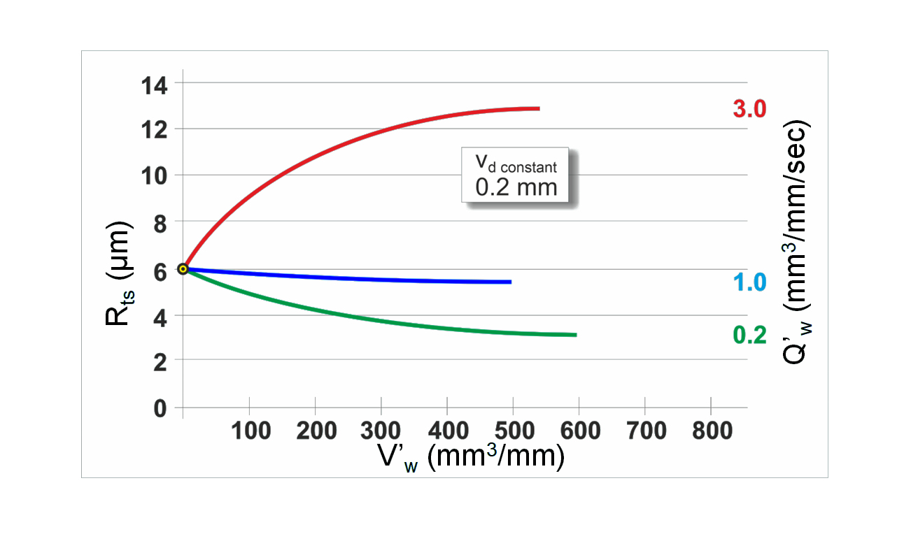
Concerning surface roughness, the dressing parameters should be set so that the grinding wheel adapts to the specified material removal rates at the start of the grinding cycle. After a certain amount of material (v'w) has been removed, each grinding wheel adjusts to its "own" surface roughness, regardless of the roughness initially dressed. Figure 1 shows how the wheel adjusts from different surface roughnesses of approximately 4 to 13 micrometers (µm) at a constant metal removal rate of Q'w 1 mm3/mm/sec, to a roughness of 6 micrometers, regardless of its initial dressed roughness. It is fascinating that this phenomenon usually occurs at a v'w of about 500 mm3 of material removed per 1 mm width of the grinding wheel.
(Source: Dissertation by K. Weinert, 1976, Technical University of Braunschweig).
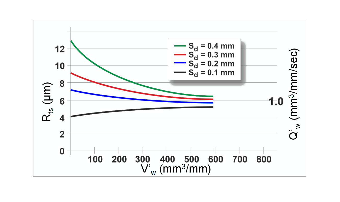
Figure 2 shows the influence of the removed material volume v'w on the original surface roughness Rts of 6 micrometers at different material removal rates Q'w and varying dressing feedrate vd per wheel revolution sd. The roughness of the grinding wheels adapts to different roughness values Rts (4 to 13 µm) at different stock removal rates (Q'w 0.2 to 3). In all three processes, the dressing was performed at constant dressing feedrate vd of 0.2 mm/revolution of the grinding wheel. The following conclusions can be drawn:
- The results show that the dressing roughness should initially correspond to the chosen removal rate, in this case, 6 micrometers.
- It can also be seen that fine surface roughness becomes rougher with higher material removal.
- The two diagrams also show that the reverse occurs when a low stock removal rate is applied: The surface roughness becomes finer than that originally dressed into the grinding wheel by dressing.
This adaptation of the grinding wheel to the material removal rates is called "self-sharpening." Under perfect process conditions, grinding wheels should only be dressed due to loss of shape or profile, but not because the grinding wheel has become clogged or blunt.
Influence of the dressing parameters infeed and dressing feedrate
To achieve an excellent surface finish and high stock removal rates, it is extremely important to work with small infeeds ad (cutting depth), i.e., 0.002 to a maximum of 0.03 mm per dressing pass.
To increase the surface roughness of the wheel, the dressing feed vd is increased and not the depth of the dressing infeed ad.
A higher dressing feedrate vd leads to a higher surface roughness of the wheel and, thus, a more aggressive grinding wheel that cuts more freely.
A low dressing feedrate vd leads to a finer grinding wheel topography and a better surface finish on the workpiece but to a lower stock removal rate during grinding. It should also be noted that grinding wheels dressed too finely can cause grinding burns.
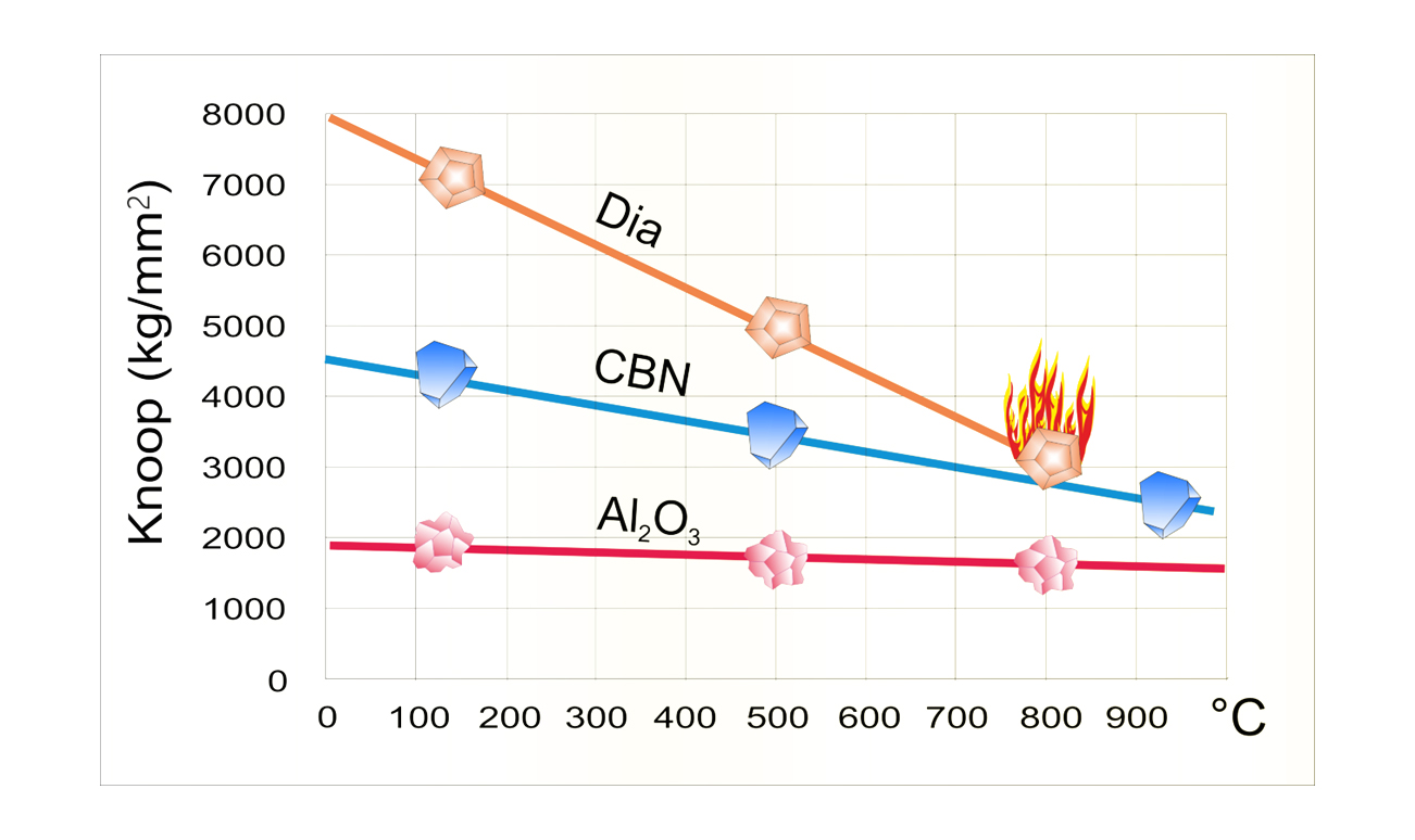
Important: Always use grinding fluid (coolant) during dressing to avoid thermal damage to the diamond; see Figure 3. In addition, the grinding wheel should never be dressed without infeed (with ad = 0 mm).
Setting the dressing parameters
Effective width bd of dressing tools
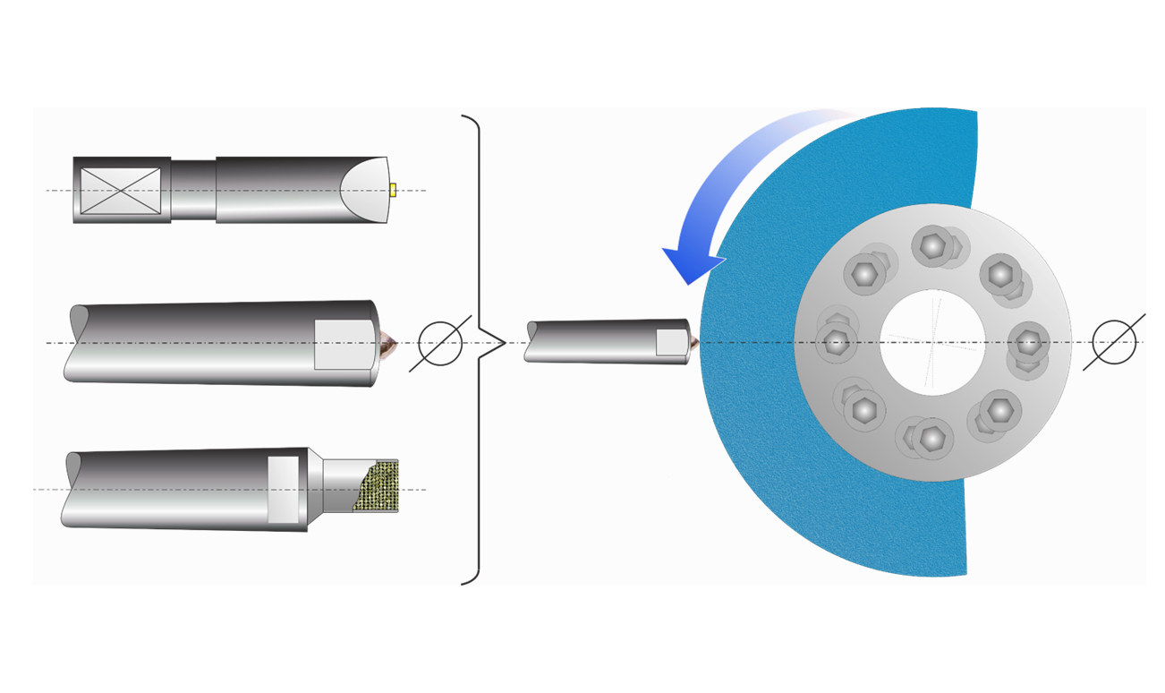
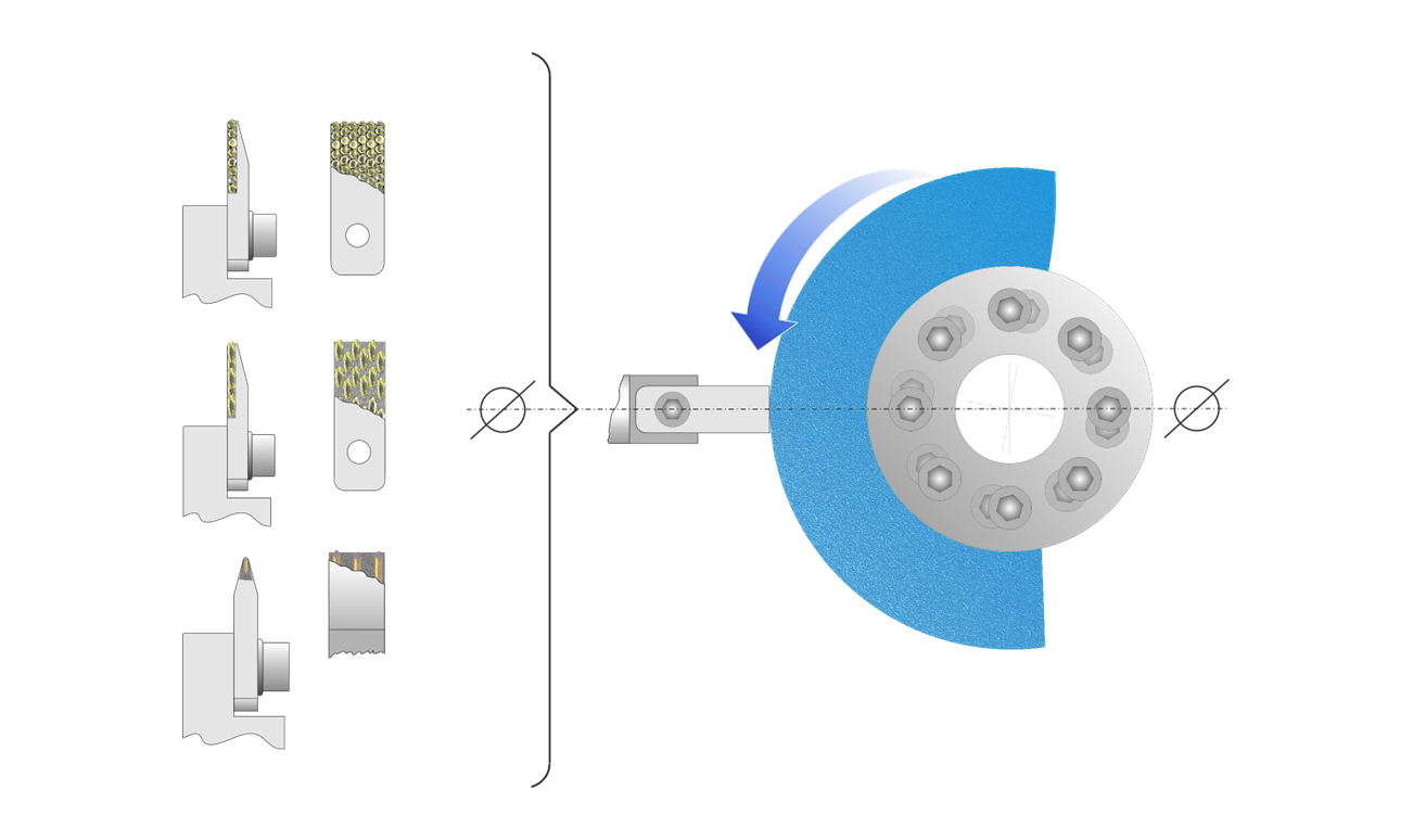
This dressing parameter specifies a diamond tool's effective width bd at a specific cutting depth ad.The ideal effective width bd is listed below for the dressing tools shown in Figure 4:
- Single-point diamonds: 0.5 to 1 mm
- Multi-point diamonds: 1.5 to 12 mm*
- Standard dressing blades: 0.7 to 1.0 (1.2) mm
- MCD or CVD dressing blades: 0.4 to 1.2 mm
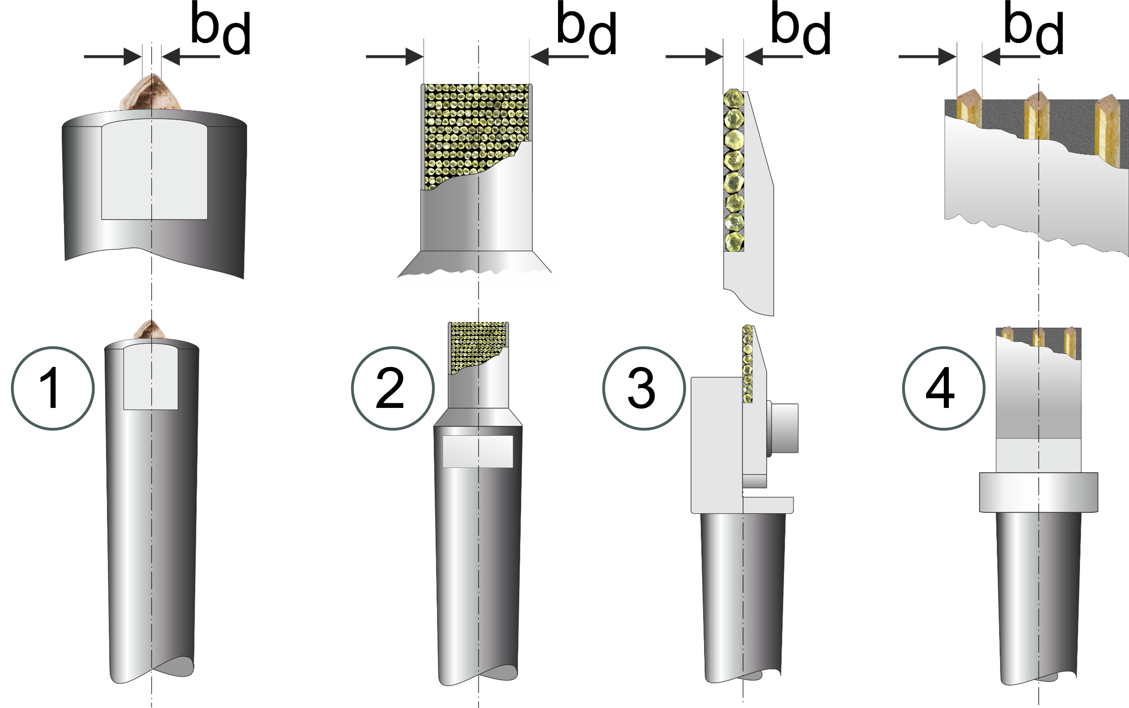
Caution*: For multi-point diamond dressers (2) with an effective width bd of more than 3 mm, only 35 % of the actual measured width should be used, as the total width of all protruding diamond points is approximately 1/3 of the measured width of the tool. If the actual effective width is used, there is a risk that the grinding wheels might be dressed too finely.
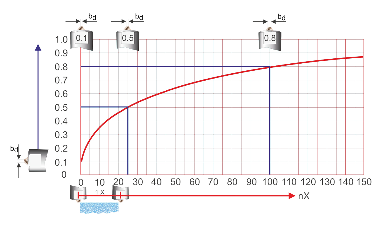
The effective width bd for single-point dressers with natural diamonds depends on the wear caused by frequent use, as shown in Figure 5. The effective width bd should never be more than 1 mm. When an effective width of 1 mm is reached, the diamond should be repositioned in the holder if the diamond has several usable points for dressing. Otherwise, the diamond should be replaced.
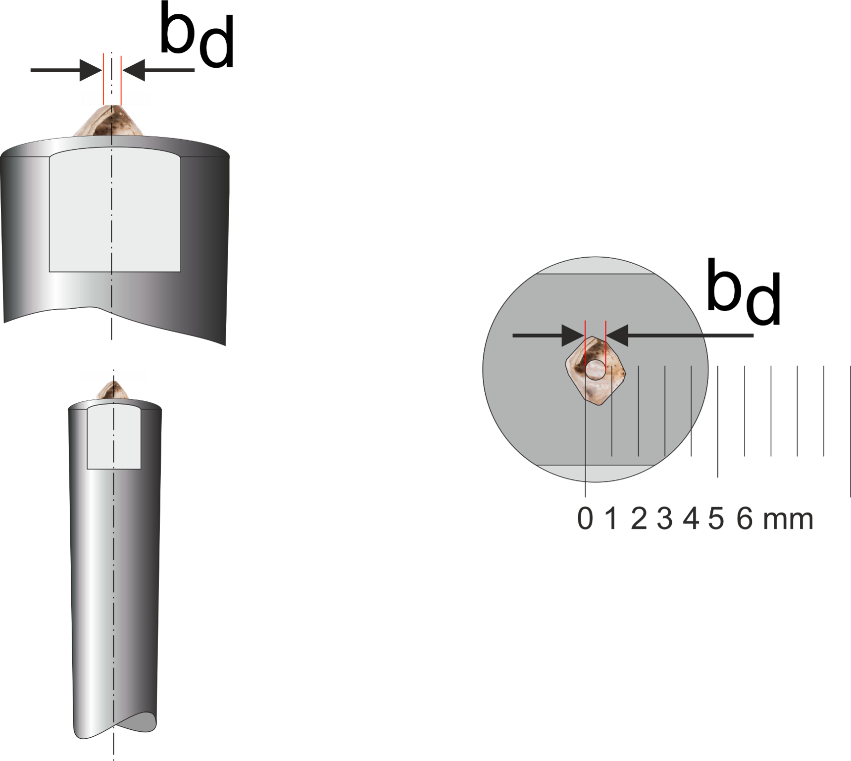
To determine the effective width bd of a single-point diamond, see Figure 6; a ruler and a magnifying glass can be used. This method provides a good reference point for calculating the correct feedrate vd.
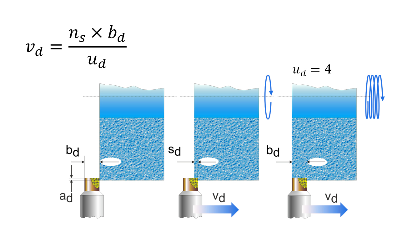
Overlap ratio ud
Figure 7 shows an overlap ratio ud of 4. The overlap ratio indicates how often a point on the grinding wheel circumference is covered by the effective width bd of the dressing tool for a certain number of wheel revolutions. The more often this happens, the higher the overlap ratio and the finer the grinding wheel surface. An overlap ratio ud of 4, as shown in Figure 7, therefore means that the dressing tool has moved axially across the wheel's width by its effective width bd in four grinding wheel revolutions.
Standard overlap ratio values:
Roughing: 2 - 3
Normal loops: 3 - 4
Finishing: 4 - 6
Fine finishing: 6 - 8
Calculation of the overlap ratio ud and speed of dressing feed vd
bd = effective width in mm
ns = grinding wheel revolutions per minute
ud = overlap ratio (number)
vd = speed of dressing feed in mm/min
The formula for calculating the overlap ratio ud
ud = Effective with of the diamond bd / Dressing feed sd per grinding wheel revolution = bd / sd = (bd x ns) / vd
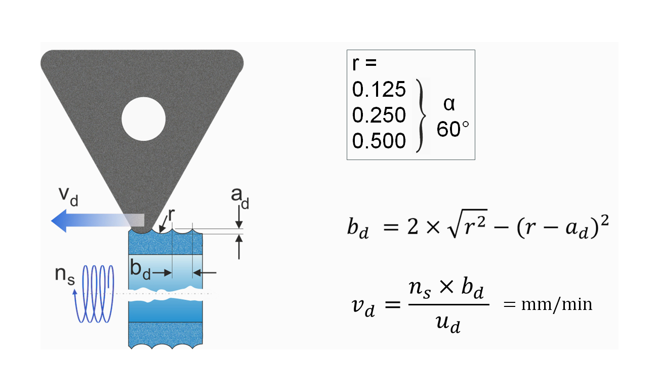
Suppose the overlap ratio ud has been determined by calculation or other selection criteria. In that case, the dressing feedrate vd of the diamond tool can be easily calculated. For dressing tools with defined radii, the dressing infeed depth ad must be used first to determine the effective width bd, see Figure 8.
vd = (ns × bd) / ud
Calculation of the dressing feedrate vd for dressers with a defined radius
The formula shown in Figure 8 also applies to all dressing tools with a defined radius.
Dressing depth ad
As mentioned, the depth infeed ad per dressing pass should not exceed the range of 0.002 to 0.03 mm for all stationary dressers.
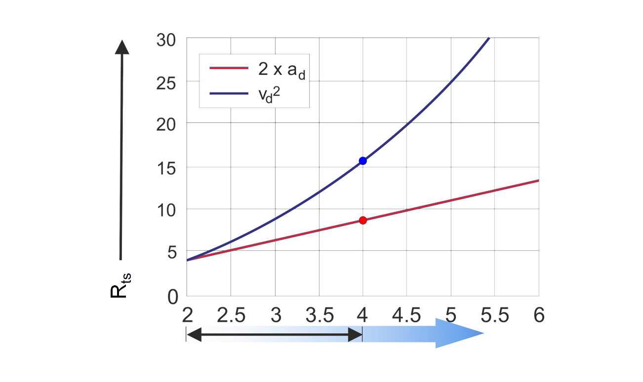
Dressing feed vd versus depth infeed ad
Is it better to increase the dressing feedrate vd or the infeed depth ad to obtain a more aggressive grinding wheel? Figure 9 shows the effect of doubling the feedrate vd and the infeed depth ad on the surface roughness Rts of the grinding wheel. The graph shows that increasing the dressing feed vd (exponential increase) has a greater effect on the surface roughness Rts than increasing the infeed (linear increase) ad.
Positioning of dressers in relation to the center line of the grinding wheel
All stationary dressing tools should have their center point on the center line of the grinding wheel to avoid possible distortions during CNC profile dressing, as shown in Figures 10 and 11.
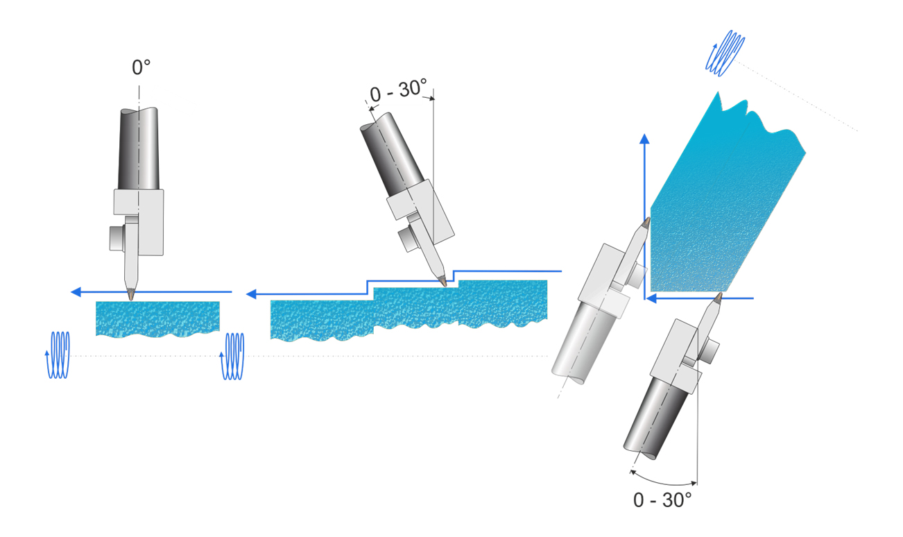
Application guidelines for blade dressers
Depending on the grinding wheel profile, blade dressers can be used in different angular positions (straight wheels, wheels with shoulders, angle plunge grinding wheels). In all cases, however, the basic rule of central positioning in relation to the wheel axis should be observed.
Do you have any questions?
Please get in touch with us if you would like to know more about setting dressing parameters. We are happy to advise you.