


Shoe Grinding – Precision For Thin-Walled Workpieces
What's the best way to achieve high roundness accuracies in thin-walled rings and sleeves? For example, when a roller bearing raceway has to be extremely precise to guarantee a long service life? How can external and internal machining be efficiently realized in one clamping so that such rings can also be manufactured cost-effectively? STUDER has both the answers and the necessary manufacturing process: Cylindrical grinding with a shoe grinding fixture, or simply said: Shoe grinding!
The Shoe Grinding Principle
The thin-walled ring-shaped workpiece, the roller bearing ring, must be clamped in such a way that it cannot be deformed and that the concentricity from external to internal diameter is determined by the clamping system.
Neither of these requirements can be achieved with a chuck (3 or 6-jaw chuck). In addition, the entire external and internal contour should be machined in one clamping as far as possible. The use of a magnetic chuck usually requires concentric truing of each individual workpiece using a dial indicator, which is time-consuming and incompatible with automatic loading. This in particular, represents a major obstacle for the mass production approach required in the roller bearing industry.
The best way to hold thin-walled rings is to use a method that completely separates the workpiece support from the rotary drive (workpiece drive):
- Shoe grinding fixture for supporting the workpiece;
- Electromagnetic chuck for torque introduction, drive and fixing of the workpiece.


2. Horizontal support shoe
3. Vertical support shoe
4. Electromagnetic chuck
5. Magnet pole boosters
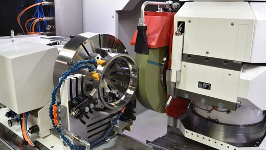
Configuration of the shoe grinding fixture
The illustration above shows a universal shoe grinding fixture. The workpiece was deliberately omitted to allow for better visibility of the assembly.
STUDER universal shoe grinding fixtures are available in several usefully graded sizes, covering a diameter range from 10 to 460 mm.
In addition to the universal shoe grinding fixtures shown, there are also versions for the mass production of part families, which allow quick changeover to a new workpiece using quick-change jaw plates.
Key:
1. The shoe grinding fixture is clamped to the workpiece table and is movable in the Z direction.
2. The horizontal supporting shoe is an oscillating shoe design, with universal sliding inserts with fine adjustment.
3. The vertical supporting shoe is a fixed shoe design, with universal sliding inserts with fine adjustment.
4. Electromagnetic chuck, shown here with radial poles, is for the workpiece rotation and for fixing of the workpiece.
5. Magnet pole boosters. These are regularly reground in the assembled state to ensure the flatness and perpendicularity of the magnet contact surface. They are radially adjustable and clamped in the T-slot.
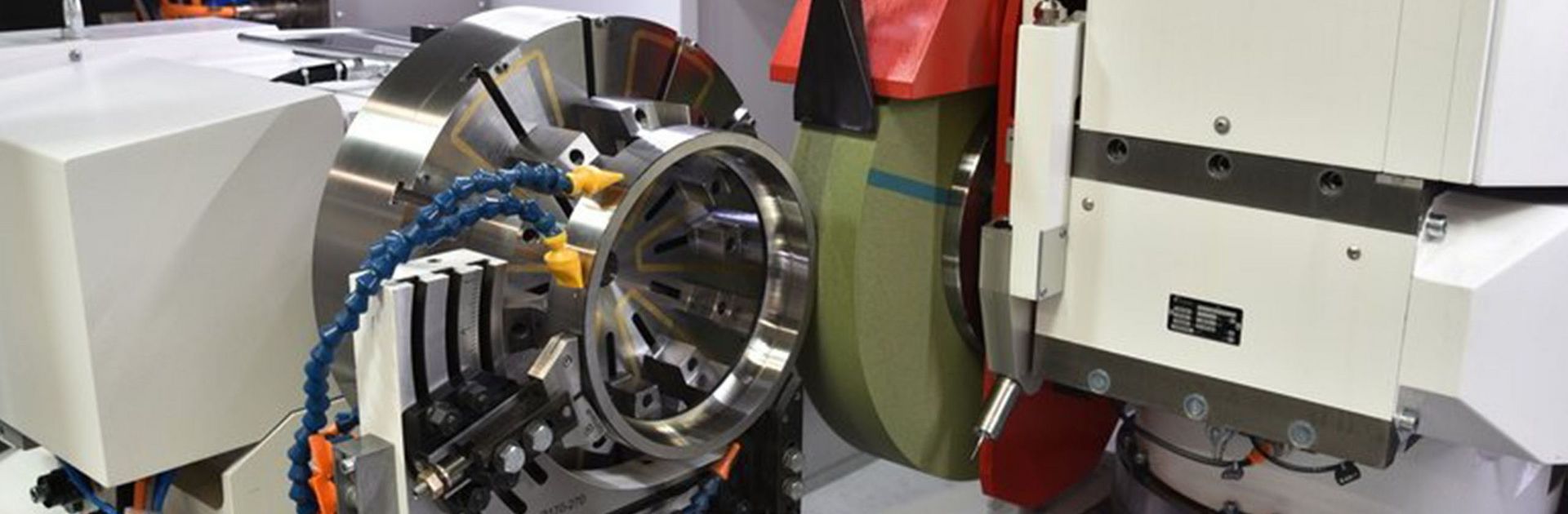
Setup of the electromagnetic chuck

The electromagnetic chuck drives the workpiece in the direction of rotation and thus generates the workpiece speed. In addition, the chuck holds the workpiece in its nominal position through contact with the face of the workpiece. This is exactly where a small relative movement takes place between the chuck (pole booster, pole ring) and workpiece face, because the centerline of the support shoes is positioned off-center: Depending on the workpiece size, either concentric poles or radial poles are selected, with concentric poles being common for smaller workpieces (up to approx. 80 mm).
Concentric pole electromagnets can have various fastening hole patterns to match any available product range of a customer. The driving and holding force of the electromagnetic chuck can be programmed in different steps. This means that the holding force for particularly delicate operations can be briefly reduced via the CNC program and subsequently increased when a higher clamping force is needed in the same program. The magnetic force can be programmed on the magnet control unit individually in 16 different steps. If several electromagnetic chucks must be used, the electrical connection is made with plug contacts directly behind the chuck.
Possible Wheelhead Configurations
The uppermost priority is to finish grind a bearing ring externally and internally: perfect concentricity external to internal diameter, uniform manufacturing temperature for greater dimensional stability; reduction of the amount of "working capital“, etc. This means that the wheelhead should be equipped with the grinding tools required for the entire process: External grinding wheel(s), internal grinding wheel(s), measuring probe. Of course on an infinite, high-precision B-axis, with an angle repetition accuracy of 1" (e.g. with the S41).
Achievable Precision
The table shows what can be achieved with a shoe grinding attachment on a STUDER cylindrical grinding machine. These values have been confirmed with various customer projects and internal tests, however the blanks must have perfect flatness on the clamping side (face left).


Interested in More?
Want to learn more about shoe grinding? The experts from UNITED GRINDING will be happy to advise you!