


Avoiding grinding burn
Excessive heat development in the grinding process can lead to thermal damage to the workpiece, often necessitating the disposal of the affected components. Read this motion blog to learn how this heat build-up occurs and how to detect and avoid it.
Definition of grinding burn
Let us begin by understanding the concept of grinding burn and its underlying causes. In grinding hardened steel, most of the energy delivered by the grinding spindle is transformed into heat. Ideally, in grinding processes, this generated heat should be efficiently removed by the chips produced and the application of coolant. However, if this heat is not dissipated effectively, it penetrates the workpiece, potentially leading to alterations in structural or surface properties, a phenomenon recognized as grinding burn or thermal damage. Such modifications can precipitate the development of grinding cracks and induce tensile stresses. Upon identification, these issues necessitate the disposal of the affected components to prevent the grave risks associated with the deployment of faulty components in critical applications, including engines, turbines, and machinery.
Development of grinding burn
Grinding burn is a multifaceted phenomenon influenced by an array of factors. To prevent grinding burn, it is imperative to choose the right grinding parameters, utilize appropriate grinding wheels, ensure effective cooling, comprehend the material properties, have proficiency in operating the grinding machine, and execute the grinding process with expertise. Diligent monitoring and precise adjustment of these elements can enhance the quality of the grinding outcome and minimize the risk of damage.
The primary causes of grinding burn are outlined below:
1. Incorrectly selected grinding parameters
The grinding wheel's surface speed (vc), in meters per second, is a critical parameter for all grinding processes. A fundamental principle suggests that a grinding wheel rotating at higher speeds results in shorter contact times with the workpiece, which, under certain conditions, may lessen the risk of grinding burn. This reduction, however, depends on having adapted the process for high speeds with adequate cooling capacity. Conversely, an elevated peripheral speed might render the grinding wheel excessively hard, increasing the susceptibility to grinding burn. Thus, a comprehensive understanding of the grinding process is indispensable. Therefore, the risk of grinding burn can often be mitigated by lowering the grinding wheel's surface speed (vc). Other parameters influencing grinding burn during cylindrical grinding are the workpiece speed in RPM (nw) and the feed rate in the plunge-cut process (vf) in millimeters per minute. In the case of OD cylindrical traverse grinding, significant parameters include the infeed (ae) in millimeters per pass and the traverse feed rate (vfa), in millimeters per minute. Adjusting these parameters — whether set too high or too low — can significantly affect the occurrence of grinding burn.
In the context of surface or creep-feed grinding, the table speed (vw) and the depth of cut (ae) per pass, are crucial parameters. The speed ratio (qs) between the grinding wheel and the workpiece is a key factor in configuring the process. For cylindrical and surface reciprocating grinding, the speed ratio (qs) typically ranges from 60 to 80 and should not surpass 120 to avoid an increased risk of grinding burn. A speed ratio of 80 indicates that the surface speed of the grinding wheel is 80 times greater than that of the workpiece. In creep-feed grinding scenarios, the speed ratio should exceed 1,000, but for optimal safety and effectiveness, starting at a speed ratio of 1,500 is advisable to reduce the risk of grinding-induced burn significantly.
2. Cooling lubricant supply and nozzle design
The exit speed of the coolant (Vkss) should ideally match the surface speed of the grinding wheel (vc), a practice referred to as equal coolant velocity delivery. Deviations from this, whether lower or higher nozzle exit speeds, can markedly elevate the risk of grinding burn. It is critical to position the nozzle such that the coolant jet is tangential to the grinding wheel's circumference, ensuring it contacts the wheel before reaching the interaction zone between the grinding wheel and the workpiece. An angle of attack of 20 degrees has been found effective in real-world applications. Furthermore, the nozzle's opening should be free of any rounding or damage that might disrupt the coolant jet by introducing air into it. Adopting 3D-printed steel nozzles is recommended, which can be obtained from IRPD. The following guideline is useful for estimating the required coolant flow: Qkss = approximately 1.5 - 5.0 liters per minute per millimeter of the wheel width in use, based on insights from Prof. Dr. Bernhard Karpuschewski of IWT Bremen.
3. Dressing parameters
Experience has demonstrated that improperly chosen dressing parameters frequently lead to grinding burn, particularly when the grinding wheel is dressed too finely. A finely dressed grinding wheel heightens grinding pressure and grain friction, thereby significantly increasing process heat. Simple formulas can calculate the dressing feed rates (vd) for stationary dressing tools. First, select an overlap (ud) of 4, ascertain the effective width (bd), which is typically around 0.8 mm for a blade dresser, and then use the following formula:
vd (Dressing feedrate in mm/ min) = (ns (Grinding wheel RPM) x bd (Effective width of the diamond tool in mm) ) / ud (Overlap ratio)
To simultaneously achieve an excellent surface finish and high stock removal rates, working with a small infeed (ad) or cutting depth is crucial. Therefore, an infeed ranging from 0.002 to 0.03 mm per dressing pass should be selected. To enhance the wheel's surface roughness and cutting capability, the dressing feed rate (vd) should be increased rather than the depth of the dressing infeed (ad). A speed ratio (qd) between 0.6 and 0.8 in synchronous dressing mode is recommended when using rotating dressing tools. This specific ratio range ensures that a cutting grinding wheel is less prone to cause grinding burn.
qd (Speed ratio) = VR (Surface speed of the diamond roll) / VC (Surface speed of the grinding wheel)
4. Grinding wheel specification
Selecting inappropriate specifications for grinding wheels can also lead to grinding burn. The finer the abrasive grain, the greater the grinding pressure and the heat transferred into the workpiece. Grinding wheels that are too hard due to a high bond content increase the risk of burning as the bond material does not grind but contributes to excessive friction. Wheels with closed structures offer limited pore space, allowing only a minimal amount of coolant to reach the grinding zone. In such cases, consulting with the wheel supplier is advisable. For creep-feed grinding, highly porous, soft, and low bond content specifications are essential to avoid grinding burn. Additionally, porous grinding wheels are recommended for OD cylindrical angle plunge grinding when the workpiece's shoulder height exceeds 7 mm to ensure efficient cooling and chip removal.
5. Skills shortage or lack of grinding knowledge
The machine operators must understand the four points mentioned above and their interrelationships. If this is not the case, if this is not the case, we will be happy to assist you by offering appropriate grinding courses.
Methods of grinding burn testing
- Visual inspection
The workpiece can be inspected with the naked eye to see whether discoloration has occurred on the workpiece surface. This method is unreliable, as grinding burn may have occurred during roughing, and the discoloration is removed by the finishing operation.
- Nital etching
Nital etching is a multi-stage, non-destructive testing process suitable for hardened steels. However, this process does not apply to aerospace parts made from Inconel and similar materials. The method involves etching with diluted nitric acid and subsequent bleaching with diluted hydrochloric acid, which reveals grinding burn through altered shades of grey on the material.
- Barkhausen method
The Barkhausen noise test is an electromagnetic technique that identifies variations in hardness and residual stress in ferromagnetic materials, which indicate grinding burn. This method is entirely non-destructive and can be directly applied to parts on the grinding machine. However, it necessitates calibration using a workpiece free from grinding burn to ensure accuracy.
- X-ray diffraction (XRD)
This method enables the measurement of residual stresses in materials, including non-ferrous metals like Inconel and other high-performance nickel alloys commonly used in aerospace applications.
Do you have any questions?
If you have any further questions on this topic, please contact us. Our experts will be happy to help and advise you.
Example of grinding burn

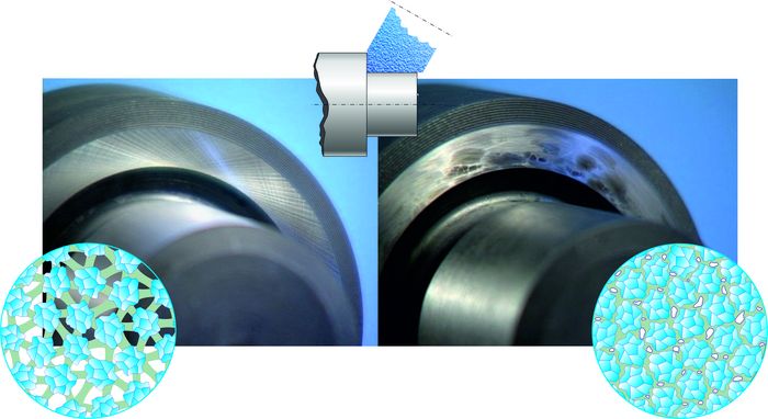

Right: grinding burn; use of closed wheel structure